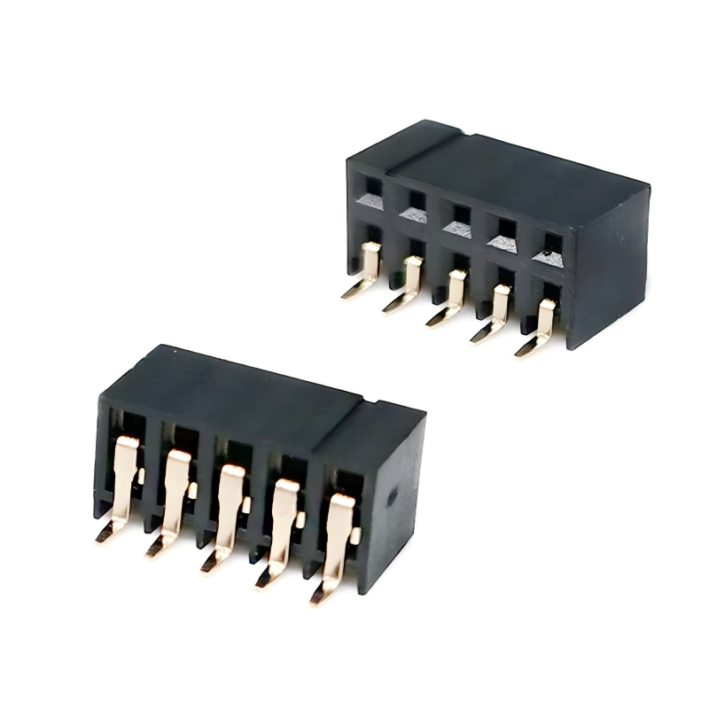
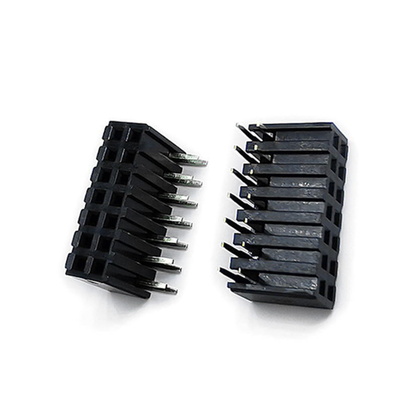
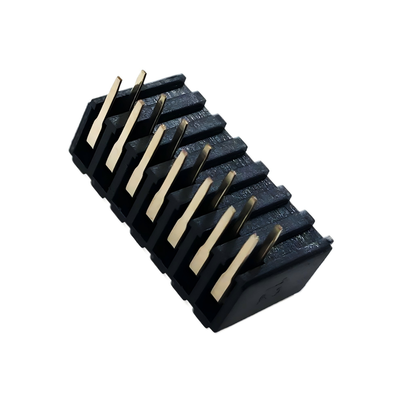
1.27 mm 2.0 mm 2.54 mm Pitch Female Header Side Insertion Type Customization Available
Product Description
| Item |
Specification |
| Product Type |
Female Header Connector |
| Connector Style |
Side Entry / Horizontal |
| Pitch Options |
1.27 mm / 2.00 mm / 2.54 mm |
| Contact Type |
Female Receptacle |
| Number of Rows |
Single Row / Dual Row / Custom |
| Number of Positions |
Customizable according to PCB design |
| Mounting Type |
THT / SMT options available depending on configuration |
| Mating Connector |
Matching Pin Header |
| Insulator Material |
Engineering Thermoplastic; material can be selected according to application |
| Contact Material |
Brass / Phosphor Bronze or specified copper alloy |
| Contact Plating |
Tin / Gold plating options |
| Insulator Color |
Black / Custom |
| Insulator Height |
Customizable |
| Contact / Pin Length |
Customizable |
| PCB Tail Length |
Customizable |
| Mating Direction |
Horizontal / Side Entry |
| Flammability |
UL94V-0 material option available |
| RoHS |
Available according to material and production configuration |
| Packaging |
Bulk / Tray / Tube / Tape & Reel depending on configuration |
| Customization |
Pin count, pitch, height, contact plating, termination and dimensions |
| Application |
Board-to-Board / Wire-to-Board / Internal PCB Connection |
Customizable PCB Connector for Board-to-Board and Wire-to-Board Applications
The 1.27 mm / 2.00 mm / 2.54 mm Pitch Female Header, Side Entry Type is a configurable PCB connector designed for applications where the mating direction needs to be horizontal or parallel to the PCB.
Available in three common pitch options—1.27 mm, 2.00 mm and 2.54 mm—the connector can be configured with different pin counts, rows, insulator heights, contact plating and termination dimensions according to the customer's PCB layout and mating requirements.
The side-entry structure is particularly useful when a conventional vertical female header would interfere with enclosure height, PCB stacking, cable routing or adjacent components.
It can be used as a mating receptacle for male pin headers in board-to-board, wire-to-board and internal PCB interconnection applications.

Why Choose This Side Entry Female Header?
1. Three Standard Pitch Options for Different PCB Layouts
The biggest selection advantage is the availability of three widely used pitch configurations:
- 1.27 mm (0.050") – for compact and relatively high-density PCB layouts
- 2.00 mm (0.079") – a compromise between board density and mechanical spacing
- 2.54 mm (0.100") – widely used for conventional PCB interconnection and standard pin-header designs
This allows engineers to select the pitch based on PCB space, mating header, signal density and mechanical clearance, rather than redesigning the connector interface around a fixed pitch.
Commercial female-header product families also commonly define 1.27 mm and 2.54 mm versions with different pin counts and row configurations.
2. Side-Entry Structure for Horizontal PCB Interconnection
Unlike a conventional vertical female header, the side-entry female header changes the mating direction to the side.
This can be useful when the equipment enclosure has limited vertical clearance.
Typical design considerations include:
- PCB stacking;
- Horizontal module insertion;
- Restricted enclosure height;
- Parallel PCB arrangement;
- Cable or harness routing;
- Connection to a perpendicular PCB.
For equipment designers, this means the connector can be evaluated as part of the mechanical architecture, rather than simply as an electrical component.
3. Custom Dimensions for Real PCB Designs
Standard connector dimensions do not always match a customer's PCB.
For OEM and ODM projects, we can configure the connector according to the required:
- Pitch;
- Pin count;
- Number of rows;
- Insulator height;
- Contact length;
- PCB tail length;
- Mating height;
- Plating;
- Mounting method;
- Housing dimensions.
This is particularly useful for projects where the connector must fit an existing PCB footprint or mechanical enclosure.
Industry suppliers also commonly offer customized pin length, PC-tail length, and insulator height for female-header products.
THT or SMT Side Entry?
The mounting method should be determined during the PCB design stage.
| Requirement |
Recommended Configuration |
| Traditional through-hole PCB assembly |
THT Side Entry |
| Automated surface-mount assembly |
SMT Side Entry |
| Strong mechanical PCB retention requirement |
THT may be considered |
| Reflow-based PCB production |
SMT configuration |
| Existing through-hole footprint |
THT |
| Existing SMT footprint |
SMT |
| Custom PCB design |
Select mounting method based on assembly process |
Applications
Consumer Electronics
Suitable for internal PCB connections in:
- Consumer electronic devices
- Smart home equipment
- Display equipment
- Control panels
- Embedded electronic devices
The compact 1.27 mm option can be considered where PCB space is constrained.
Industrial Control Equipment
Side-entry female headers can be used in:
- PLC-related equipment
- Industrial controllers
- Measurement instruments
- Control boards
- Automation equipment
- Industrial communication modules
The selection should be based on the required electrical rating, environment and assembly method.
Communication Equipment
Potential applications include:
- Network equipment
- Communication control boards
- Interface modules
- Signal-processing boards
- Embedded communication systems
For compact communication equipment, the 1.27 mm or 2.00 mm pitch can be evaluated when PCB density is an important design consideration.
Automotive Electronics
Potential applications include:
- Automotive control modules
- Display control boards
- Instrumentation electronics
- Vehicle interface modules
- Infotainment-related PCB assemblies
Automotive applications should be evaluated against the actual temperature, vibration, electrical, and environmental requirements rather than relying only on the connector's nominal configuration.
Medical and Measurement Equipment
The connector can also be considered for:
- Test instruments
- Measurement equipment
- Control electronics
- Diagnostic equipment
- Industrial meters
For these applications, engineers should specify the required material, contact plating, electrical rating and environmental conditions during quotation.
Engineering Selection Guide
Which Pitch Should You Choose?
| Pitch |
Typical Design Direction |
Main Consideration |
| 1.27 mm |
Compact / higher-density PCB |
Save PCB space |
| 2.00 mm |
Medium-density electronics |
Balance spacing and size |
| 2.54 mm |
Conventional PCB architecture |
Compatibility with common headers |
Our Service
Sample Availability & Policy
Samples are to be sent to our customers for free on their request, so long as they are willing to pay for the freight, or we can pay the freight for some old customers from our side as well, or the customer can pay the freight in advance, and we can ship samples with our courier as well.
Guarantees/Warranties/Terms and Conditions
We provide a product quality guarantee.
A 15-day quick delivery is assured.
Payment terms include T/T, but it is subject to negotiation, such as L/C, PayPal, Western Union, and more.
After Sales Service
Excellent service is offered through our network of offices and head office.
Please contact us by phone or e-mail, or if convenient, visit our office.
Aside from the friendly service, we offer the most competitive prices and flexible scheduling.
FAQ
Q: What's your MOQ?
A:Our MOQ usually comes to 1000 pcs, but we accept small order quantities for testing.
Q: Can I visit your factory?
A: Welcome to visit our factory, and we will show you our professional production process, and we can build long-term cooperation with you.
Q: What's your sample time? What's your delivery time?
A: 7 days for samples, and 15-20 days for mass production. It depends on the quantity.
Q : How do I inspect my goods?
A : You can inspect by visiting the factory, or ask a third party to inspect, or by picture inspection.
Q : How much does it cost to ship to my country?
A : The freight will be given by the freight company based on your Gross Weight and CBM.
Q:How do I know if you ship out my order?
A:The tracking number(DHL, UPS, FedEx, TNT, EMS, etc.), Air Waybill, or B/L by Sea will be sent to you as soon as your goods are shipped out. We also follow up on the delivery and keep you informed. The helpful after-service is provided. We support what you sell.
Q: Can I make personalized/customized products?
A: Sure, just send us your drawing or sample.

 Your message must be between 20-3,000 characters!
 english
 français
 Deutsch
 Italiano
 Русский
 Español
 português
 Nederlandse
 ελληνικά
 日本語
日本語
 한국
한국
 العربية
 हिन्दी
 Türkçe
 indonesia
 tiếng Việt
 ไทย
ไทย
 বাংলা
বাংলা
 فارسی
فارسی
 polski